What is Fused Deposition Modeling (FDM 3d Printing) and How It Works?
Fused Deposition Modeling (FDM 3d Printing) is a material‑extrusion method in which a meltable thermoplastic filament is fed into a heated nozzle, liquefied, and laid down on a build plate one layer at a time. In plain English, the raw filament is continuously extruded through the print head as the X‑Y gantry traces each slice; then either the bed drops or the head rises so the next layer can begin. The cycle starts when slicing software turns a 3‑D model into individual layers and calculates the toolpaths. Those G‑code instructions drive the motors and the extruder, building the part layer by layer.
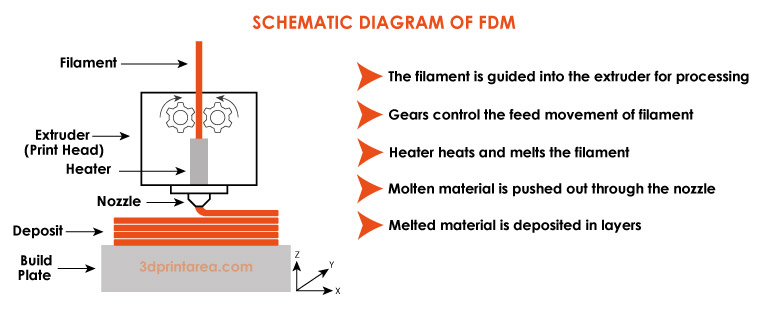
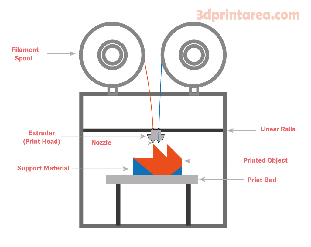
As the schematic above shows, the molten filament exits the nozzle as a thin bead and bonds to the layer below, steadily “growing” the part upward. During this climb the material cools and solidifies, locking the geometry in place. Typical layer heights range from about 0.05 mm to 1 mm: thinner layers yield smoother surfaces and finer detail, but at the cost of extra print time. For overhanging features the slicer can automatically add sacrificial supports, which are snapped off once the build is finished.
One hallmark of FDM—also known as Fused Filament Fabrication (FFF)—is the way successive roads of molten plastic fuse together, giving the part its strength as it cools. The two labels describe the same process; “FDM” is Stratasys’ trademark, while “FFF” is the community’s generic term. Thanks to their low cost and ease of use, FDM/FFF machines now make up the largest share of 3‑D printers worldwide.
FDM 3D Printing Workflow: From CAD Model to Finished Part
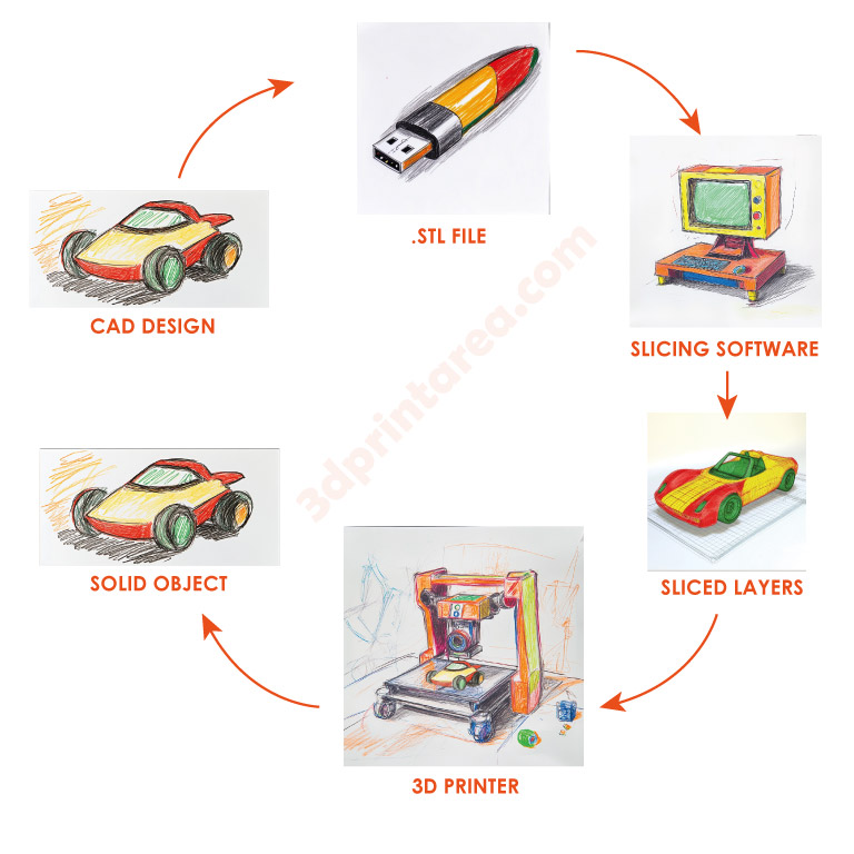
Once you have designed a component in your CAD software, the file is exported—most commonly as an STL (or increasingly, 3MF) mesh that preserves the part’s geometry. This mesh is then loaded into slicing software, which “cuts” the model into hundreds of horizontal layers and converts each layer’s tool‑paths into G‑code. The G‑code is effectively the printer’s playbook, containing every command needed to set temperatures, move the axes, control extrusion flow and, if required, generate removable supports for overhangs. The circular diagram above visualises these early stages—CAD Design → .STL File → Slicing Software → Sliced Layers—and highlights how clean geometry and the right export resolution prevent downstream artefacts such as faceting or dimensional drift.
After slicing, the G‑code is streamed or copied to the FDM printer, where the heated nozzle deposits molten filament layer‑by‑layer onto the build plate, transforming the digital stack of slices into a solid object. Each parameter chosen in the slicer—layer height, infill pattern, cooling strategy—directly affects inter‑layer fusion, surface finish and mechanical strength. Seasoned operators therefore run quick “calibration towers” to validate extrusion flow before committing to production, and they orient parts to minimise support material and maximise anisotropic properties. A brief round of post‑processing (support removal, sanding, or vapour polishing) may follow, but if the earlier steps were tuned correctly the part will already be close to its final form.
History of FDM and Its Evolution Over Time
Fused Deposition Modeling was invented in 1988 by S. Scott Crump and patented the following year; Stratasys then brought it to market. Early FDM systems were pricey, closed industrial machines, available only to well‑funded labs. Everything changed in 2009 when the core patents expired—developers could finally build printers on the same principle without paying a license fee. That legal milestone swung the door wide open for open‑source efforts such as RepRap and triggered a DIY 3‑D‑printer boom; machine prices dropped by roughly two orders of magnitude, up to 99 %.
Throughout the 2010s the RepRap movement spawned brands like Prusa and MakerBot. Desktop FDM printers flooded maker spaces and home workshops, turning FDM into the go‑to method for hobbyists. I was there for the ride: as an engineer itching to tinker, I ordered electronics from China and built my very first printer back then. 😊
A mid‑2010s survey pegged MakerBot at about 35 % of the installed FDM base, with Stratasys at 32.5 % and Prusa at 17.5 %. Today the field is even more crowded, with countless small and mid‑scale manufacturers—brands we’ll explore in a moment.
Because Stratasys still owns the “FDM” trademark, the open‑source community leans on the FFF label. In short, patent freedom and open innovation propelled the technology from a niche industrial tool to something everyone—from weekend makers to Fortune‑500 factories—can tap into.
Standards and Scientific Sources
International terminology and standards for 3‑D printing come from bodies like ISO and ASTM. Chief among them, ISO/ASTM 52900 splits additive‑manufacturing tech into seven families; the Material Extrusion bucket is where FDM/FFF lives, describing any process that deposits molten thermoplastic in layers. In other words, the official playbook classifies FDM as a material‑extrusion method. Using the same language keeps vendors and researchers on the same page. Case in point: even though FDM is Stratasys’ trademark, the standard refers to the broader workflow as Material Extrusion (MEX) and lists FDM/FFF as sample technologies in that category.
Another slice of the standards pie sets out how to test and verify printed parts. When you want to compare mechanical properties, you still lean on the usual suspects. Say you need tensile strength for an FDM piece—you’d run an ASTM D638 pull test. Impact toughness? ASTM D256. Flexural strength? ASTM D790. Journals routinely quote results from these protocols to profile FDM parts, and the numbers sprinkled through this guide (strength, modulus, you name it) all trace back to studies that followed the relevant material specs.
Design has its own rulebook, too. ISO/ASTM 52910 sketches the ground rules for shaping parts that will be additively built—think bridge lengths, support angles, minimum feature size, that sort of thing. File formats and machine code also fall under the “play nice together” banner: STL and AMF/3MF are the go‑to model files, while slicers spit out universal G‑code that just about every FDM printer understands. The upshot? Smooth teamwork between different machines and software.
Components and Mechanical Structure of FDM Printers
An FDM 3D printer blends a coordinate‑controlled motion system with an extrusion unit that lays down molten plastic one layer at a time. Most desktop machines rely on a Cartesian layout, where the print head (or build plate) shifts along the X, Y and Z axes to position material precisely. Popular variants reposition the nozzle in the X‑Y plane while the bed travels up and down on Z.
Alternative kinematics exist as well. A CoreXY platform drives X‑Y motion with two synchronized motors; Delta printers locate the head through three articulating arms; less common SCARA or polar designs use rotary joints. Regardless of the geometry, the core ingredients stay the same.
Frame & Chassis – The frame is the printer’s backbone. Whether it’s built from aluminum extrusions, sheet‑metal enclosures, or acrylic panels, a rigid chassis damps vibration and directly boosts surface finish.
Linear Motion Assemblies – Rails, rods, bearings and belts (or lead screws) guide each axis. Makers commonly pair belts and linear bearings on X/Y, with trapezoidal screws on Z. Stepper motors push those axes with roughly 10 µm theoretical resolution—real‑world repeatability depends on build quality.
Extruder – The drive system grips, feeds, and melts the filament. It has a cold end and a hot end. In a direct‑drive setup the stepper and hobbed gears sit right on the hot end—great for flexible TPU. A Bowden arrangement parks the motor on the frame and pushes filament through a PTFE tube, trimming moving mass. Either way, a calibrated extruder governs flow rate and print consistency.
Above the nozzle, a heat break and heatsink fan confine melting to the tip. A heater cartridge and thermistor (or thermocouple) keep the nozzle around 200 °C for PLA or 240 °C for ABS via PID control. The plastic stream bonds to the previous layer and solidifies almost instantly.
Build Platform – Parts grow on a flat bed, often glass or milled aluminum, clad with PEI, textured spring steel, or plain painter’s tape. Many beds are heated—about 60 °C for PLA and up to 110 °C for ABS—to fight warp. Mesh‑bed leveling probes map height variations so the first layer stays flawless. Some designs raise the bed step‑by‑step, others lift the whole gantry; the goal is a fixed nozzle‑to‑layer gap.
Electronics & Firmware – A microcontroller board interprets the slicer’s G‑code, drives steppers, regulates heaters and fans, and listens to sensors. Open‑source Marlin rules the desktop scene, served via LCD dials, touch screens, USB, SD‑card or even Wi‑Fi with camera monitoring on premium rigs.
Auxiliary Hardware – A part‑cooling fan sharpens PLA overhangs; enclosed chambers stabilize ABS. Filament‑runout switches pause the job if material runs dry. Thermal fuses and firmware safeguards reduce fire risk—peace of mind every maker appreciates.
Most hobby‑grade FDM printers share these bones. Industrial systems, though, scale up with sealed heated chambers and high‑temp polymers like Ultem™. Whether desktop or factory‑floor, real‑world print quality ultimately tracks back to sturdy mechanics, sharp calibration and smart material choices.
FDM 3D Printing Materials and Their Key Traits
In FDM printing, thermoplastic polymer filaments steal the spotlight. Because they melt when heated and solidify as they cool, these plastics can cycle through heat‑up / cool‑down over and over, laying down tidy layers in the process. Below is a quick tour of the most popular FDM materials and what makes each one tick.
PLA (Polylactic Acid)
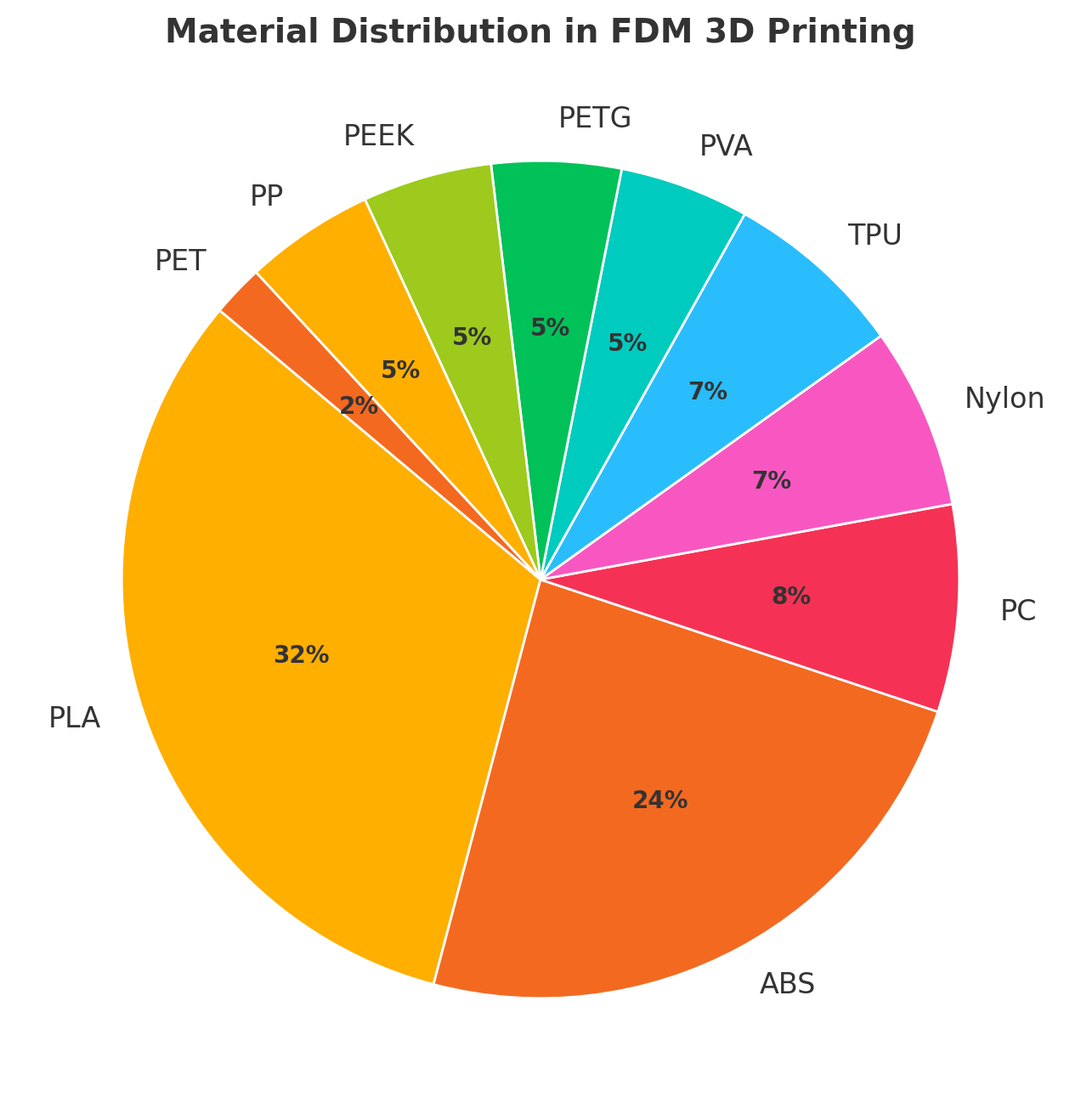
A plant‑based bioplastic (think corn starch) with a low melt range (~180–220 °C) and a glass‑transition near 60 °C. Translation? It prints like a dream. Eco‑friendly and biodegradable, PLA is pleasantly stiff but not super flexible, and it starts to soften at roughly 50–60 °C. Thanks to minimal warping and rock‑solid dimensional accuracy, it’s a go‑to for beginners and prototyping. Fun fact: one global survey put PLA at the very top of the usage charts, clocking in at about 32 % of all prints. Test coupons have shown tensile strengths around 48 MPa, which isn’t too shabby for a “simple” plastic.
ABS (Acrylonitrile Butadiene Styrene)
A petroleum‑based engineering stalwart that melts near 230 °C and hits its glass transition at about 105 °C, so it laughs at temperatures that make PLA squirm. It’s tough, impact‑resistant, and holds up better under heat (tensile strength hovers around 40 MPa). The catch? It loves to warp. You’ll need a toasty bed (90–110 °C) and, ideally, an enclosed chamber. Ventilation matters too, because molten ABS gives off styrene fumes. On the bright side, you can vapor‑polish the surface with acetone for a glossy finish. No surprise it’s the runner‑up in global popularity at roughly 24 %, powering everything from automotive mock‑ups to electronics housings.
PETG (Polyethylene Terephthalate Glycol‑Modified)
Think of PETG as PET’s cooler cousin with glycol sprinkled in. It prints at roughly 230 °C, behaves almost as easily as PLA, yet offers mechanical strength edging toward ABS territory. Shrinkage is mild, so warping rarely rears its head, and the material is pleasantly tough and semi‑transparent. Downsides? PETG loves to string, so dial in retraction settings. It shines in outdoor parts, food‑safe containers, and protective gear where a dash of flexibility is a bonus.
TPU (Thermoplastic Polyurethane) & Other Elastomers
Need rubbery parts? TPU, commonly in Shore 95A, prints between 220–250 °C. Its flexibility makes it tricky: the filament can buckle in a Bowden tube, so a direct‑drive extruder and slow speeds are your friends. Finished parts boast terrific abrasion resistance and can shrug off impacts—ideal for gaskets, phone cases, or drive belts. Just know that very fine details may “bounce” around during printing thanks to that same elasticity. Relatives like TPE and TPC cover similar ground.
Nylon (Polyamide)
Grades like PA6 and PA12 crank up strength and wear resistance but demand serious heat (about 250–260 °C). Nylon loves moisture, so keep the spool bone‑dry—otherwise you’ll get bubbly surfaces and weak inter‑layer bonds. A heated bed (~60–70 °C) and enclosure tame shrinkage. Bonus: nylon parts can be annealed after printing for even better toughness, making them favorites for gears, hinges, and living‑hinge prototypes.
PEEK and Other High‑Performance Thermoplastics
PEEK is the heavyweight champ of FDM, melting around 343 °C with a glass‑transition at 143 °C. Only purpose‑built printers with 400 °C hot ends and 120 °C chambers need apply. The payoff? Parts that shrug off 150 °C service temps and a cocktail of chemicals—perfect for aerospace, automotive, and even medical implant trials. Similar overachievers include PEI (Ultem) and PPSU. They’re pricey and finicky, so most makers wheel them out only for mission‑critical jobs.
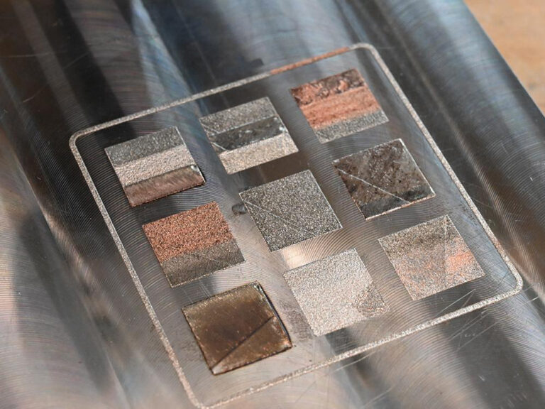
Other Players & Composites
FDM also hosts polystyrenes (HIPS, ASA), polypropylene (PP), polycarbonate (PC), and hybrids packed with carbon or glass fibers—or even wood dust for a jazzy look. ASA mimics ABS but laughs at UV, making it a darling for outdoor hardware. HIPS often doubles as a dissolvable support when paired with ABS (a quick bath in limonene sets it free). Fiber‑filled filaments give parts a boost in stiffness or visual flair but will chew up brass nozzles—hardened steel is the safer bet. Stats suggest PLA and ABS still own over half the market, with PETG, nylon, and TPU trailing. High‑performance exotics capture only a sliver, yet they’re irreplaceable when failure isn’t an option. Bottom line? Choose your filament with the end‑use firmly in mind—material fit is half the battle in nailing a print.
Experiments and Findings in Scientific Articles on FDM 3D Printing Materials
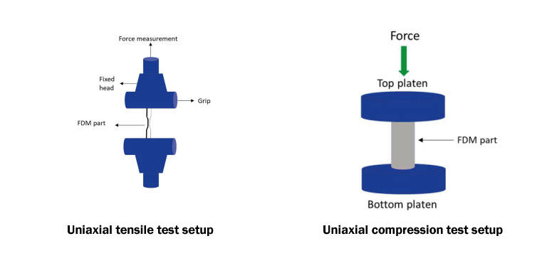
King Fahd University of Petroleum & Minerals (KFUPM) Department of Mechanical Engineering and its partner research centers published a sweeping 2024 review in Composites Part C: Open Access that pulls together tensile, compressive, and flexural data for virgin polymers printed with FDM. Stress–strain results for ASTM D638 specimens are compared across the literature, and the authors drill down into how process variables—layer height, raster angle, infill density, and so on—shape mechanical performance.
Acrylonitrile Butadiene Styrene (ABS)
Tensile test
Peak strength showed up when layer height sat at 0.2 mm and the raster angle at 15°. XY‑oriented coupons pushed as high as 26–34 MPa. As infill nudged toward 100%, voids all but vanished, leaving a denser micro‑structure that carried more load before finally letting go.
Compression test
Fully‑densified ABS hit roughly 51 MPa in compression, but samples with sparse or patterned infill dropped to about 23–25 MPa. A gyroid core paired with a 0° raster kept fibers lined up and porosity locked down, delivering the best crush resistance.
Polylactic Acid (PLA)
Tensile test
Dialing the layer height down to 0.1 mm and cranking the raster to 90° lifted tensile strength to roughly 47 MPa. Prints in the X‑orientation, where fibers run right along the load path, felt the stiffest; Y‑oriented or 45° parts lagged by up to 20 %.
Compression test
Long cylindrical specimens clocked compressive yield between 45 and 49 MPa. The bigger the diameter‑to‑height ratio, the better the yield and elastic modulus. Smaller prisms, on the other hand, caved early thanks to edge‑driven stress risers.
Polyether Ether Ketone (PEEK)
Tensile test
Against ABS, PEEK piles on about 120 % more muscle, brushing the 100 MPa mark. Instead of necking, it snaps straight across the raster—textbook behavior for a highly crystalline polymer with rock‑solid layer fusion.
Compression test
Under identical print settings, PEEK posts roughly 60 MPa in compression—almost double ABS. Credit the limited void space and a semi‑crystalline phase that moves the load around with ease.
Polyethylene Terephthalate (PET)
Tensile test
Literature lists fully‑dense PET at about 49 MPa in tensile yield, stiffness hovering close to that of ABS. Swap in exotic infill patterns and that number can swing ±10 %.
Compression test
Solid PET parts clock 31 MPa in compression, yet versions peppered with circular voids sag to the low 20s. Square perforations share the load more evenly, landing in the middle (~23 MPa).
Polyethylene Terephthalate Glycol (PETG)
Tensile test
PETG printed at 0° raster rises to 44 MPa, but Z‑built parts—layers stacked perpendicular to the load—see up to a 65 % hit. Cranking the nozzle to 250 °C smooths fusion and bumps ductility by roughly 30 %.
Compression test
Y‑oriented coupons act stiff yet brittle (≈1.5 GPa modulus, 12 MPa yield). Flip to the X‑orientation and modulus drops to 0.7 GPa while yield and ultimate creep up to 23 MPa, soaking up more impact.
Nylon
Tensile test
At 100 % infill and a 0.1 mm layer height, Nylon 6 lands in the 43–45 MPa zone, while a lab‑grade filament (AQ2700) stretches to ~77 MPa. Lower infill chips away at strength in a near‑linear slide.
Compression test
No ASTM‑D695‑compliant compression data yet—most work has stuck to flexure and impact. That gap is still wide open for researchers.
Thermoplastic Polyurethane (TPU)
Tensile test
Cranked to 215 °C with a 0° raster, TPU pulls in 46 MPa tensile strength and an eye‑watering 700 % elongation. Tweak temperature or raster and the toughness–strength balance shifts in a heartbeat.
Compression test
Everyone assumes TPU would gulp up energy under load, but so far, no published compression results—another blank spot on the map.
Conclusion
Stack the polymers side‑by‑side and PEEK dominates, flirting with 100 MPa in tension and towering in compression. Nylon 6’s lab‑tuned ~77 MPa makes it a contender, yet moisture sensitivity and scarce compression numbers keep designers on their toes. PLA remains easy to print but brittle; ABS and PETG strike that middling strength‑vs‑machinability bargain. TPU may sit mid‑pack on strength, yet its 700 % stretch makes it the go‑to for shock‑absorption jobs.
Under compressive loads, PEEK and PLA keep their shape thanks to semi‑crystalline order. ABS and PETG act at the mercy of infill geometry, while TPU and Nylon are still waiting for solid compression datasets. Across the board, layer alignment, infill rate, and raster angle call the shots—and with savvy parameter tuning, you can paper over most material limits.
FDM Testing Tips for Beginners
- 100 % Infill – A denser core means a tougher part; for tensile or compression trials, full infill is the safest play.
- Layer Height (0.1–0.2 mm) – Thin layers weld together more tightly, pushing overall strength upward.
- Raster Angle – Run fibers parallel to the load (0° or 90°) and watch tensile strength climb. Cross‑hatched angles trade off stiffness for ductility.
- Print Orientation – Stick to the XY plane when you can. Vertical (Z‑axis) prints invite delamination cracks.
- Filament Drying – Hygroscopic filaments like PLA or Nylon love to drink in moisture. Dry them at 50–60 °C before printing to keep parts strong.
Armed with these basics—whether you’re running ABS or PEEK—hitting your target strength in FDM prints gets a whole lot simpler. Even first‑timers can bank on safe, reliable results!
Print Parameters and Optimization
Success in FDM printing hinges on picking the right settings — and keeping them in balance. Nearly every variable you tweak in the slicer ripples through print quality, build time, and the part’s mechanical bite. Below is a plain‑English tour of the key parameters and the little tricks that help you dial them in.
Layer Height
Layer height is the big lever that sets both surface finish and production time. Thin layers (say 0.10 mm) polish the details and leave silky curves, but they’ll have your printer chugging all night. Thick layers (around 0.30 mm) breeze through a model yet can give you that tell‑tale “stair‑step” façade. Strength shifts, too: thinner layers fuse more often, so tests show that tensile strength usually dips as layer height climbs. Why? Each thick layer touches less area on the one below and cools in a slightly different rhythm. In practice, go thin when looks matter, go thick for a throw‑away prototype, and split the difference at about 0.20 mm when you need a healthy compromise.
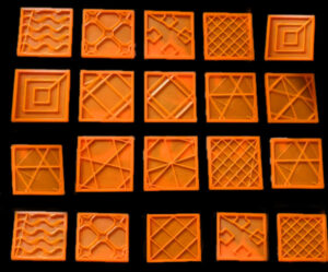
Infill Density & Pattern
Infill decides whether a part feels like a brick or a feather. A solid 100 % fill makes a bulletproof block; drop to 20 % and you’re printing a lightweight lattice. Across the board, denser infill boosts strength — a dog‑bone printed at 100 % pulls far harder than the same shape at 20 %. The trick is not to overdo it: most functional prototypes thrive at 20–50 %, especially if you thicken the walls instead. Pattern counts as well. Honeycomb and triangles absorb impacts nicely, while gyroid spreads loads evenly in every direction. Always match pattern and density to how the part will be stressed.
Print Speed
Speed rules the clock, plain and simple. Push the nozzle too fast and you may sling plastic at corners, hear steppers skip, or end up with infill that barely meets the walls. Slow down and you’ll capture crispy details and stronger layer bonds because each strand lands hotter on its neighbor. A garden‑variety desktop machine behaves happily at 40–60 mm/s; a tuned CoreXY on linear rails can sprint past 120 mm/s. Remember, every material has a sweet spot: TPU hates haste, PLA forgives a bit more rush. If you’re chasing speed, soften the accelerations and jerk settings or you’ll see ripples. Most makers run a quick tower at three or four speeds to sniff out the sweet number.
Nozzle & Bed Temperature
Right temperature, happy plastic. Too cool and layers barely kiss; too hot and you’re stringing filament like cotton candy. Stick close to the filament vendor’s window—about 200 °C for PLA, 240 °C for ABS, 250 °C for nylon, and a welding‑torch 400 °C for PEEK. Faster prints often need a nudge upward because the filament spends less time soaking in the hot zone. Bed heat is your warping insurance: start a tad high for the first layer (PLA 65–70 °C, ABS 95–110 °C), then back down a few degrees once the part is anchored. Stable temps are everything, so keep drafts out and let the PID loop do its thing.
Print Orientation
Where you park the model on the build plate decides how strong it is and how pretty it looks. FDM parts are anisotropic: they’re tougher in‐plane (X‑Y) than along Z because layer bonds are the weak link. So line up the main load path parallel to the layers whenever you can. A hook, for instance, should pull along the layers, not peal them apart. Orientation also drives support usage—tilt the part so overhangs are gentle and you’ll save both time and surface cleanup. Watch for warping: a big flat face riding the bed loves to curl; stand it up and the risk drops fast. For gnarly objects, split the model, print pieces in optimal directions, then bond them after the fact.
Other Slicer Tweaks
Beyond the headliners, slicers hide dozens of dials. Extra perimeters beef up walls but stretch print time. Skimp on top layers and you’ll spot little moons of infill peeking through. Retraction distance plus speed keeps hairy strings at bay, especially when printing a forest of skinny posts. Support angle, density, bridge flow, fan timing—they all pop into relevance under the right geometry. The golden rule? Start with a proven profile for your printer‑filament combo, then nudge one variable at a time while watching a small test piece. Experience beats any rule‑of‑thumb chart.

FDM 4D Printing Technology
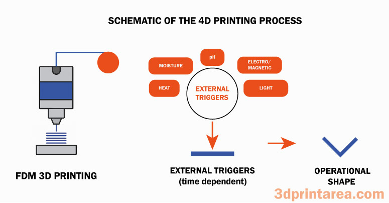
The idea of adding time—the so‑called “fourth dimension”—to 3‑D printing has become one of the field’s hottest talking points over the past decade. In short, 4‑D printing is about making 3‑D objects that keep on living: hit them later with heat, light, or moisture and they spring into a brand‑new, pre‑programmed shape. Pulling off that magic trick demands stimulus‑responsive “smart” materials born in modern materials science.
In most 4‑D workflows the hardware is nothing exotic—often the same trusty FDM machine on a hobbyist’s bench—but the filament is special. Shape‑memory polymers (SMPs) or finely tuned multi‑material blends steal the show. Warm an SMP past its trigger temperature and it relaxes so you can mold a temporary form; cool it, and the part freezes; reheat it, and it snaps back like it never left home. Even humble PLA shows a hint of shape memory: bend it into an arc, warm it up again, and it tries to reclaim that curve. Researchers have used that quirk to print PLA parts that curl or bend on command. Other triggers—humidity, UV light, electric or magnetic fields—join the party as well. A hydrogel‑based filament, for instance, swells in water, letting a printed gadget paddle around all by itself.
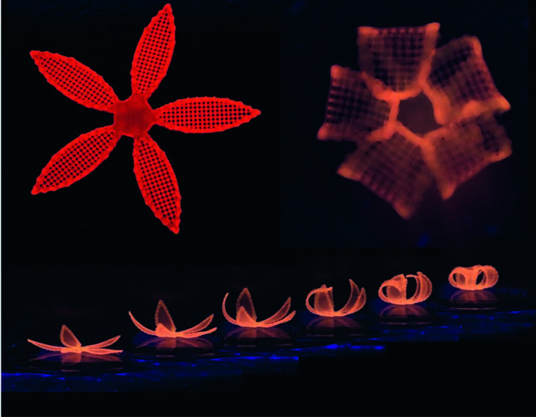
Some standout 4‑D printing demos making the rounds in recent journals include:
• Self‑folding lattices: Picture a wafer‑thin grid printed from composite ribbons; dunk it in hot water and it folds itself into a tidy box. Simply varying the print orientation layer by layer lets engineers bake different expansion rates into one material—mimicking the classic bimetal strip.
• SMP + SMA hybrids: In Kang et al.’s work, a shape‑memory nylon part printed by FDM is threaded with Nitinol wire. A brief electric pulse heats the wire, it contracts, and the plastic bends; cut the current and everything straightens out again. The fully reversible motion offers a tantalizing glimpse of future soft robots.
• Multi‑material ribbons: By laying down contrasting materials end‑to‑end, researchers build a strip that spirals under a single stimulus. One face is hydrophobic, the other loves water; immerse the strip and only the hygroscopic side swells, twisting the ribbon around itself.
The real promise of 4D printing lies in adaptive, almost “living” structures. Nature is full of inspiration—sun‑tracking flowers or pinecones that pop open in the rain—so engineers are borrowing the playbook. Temperature‑sensitive valve seals, humidity‑driven ventilation fins, body‑heat‑activated medical stents: all are under active investigation. Dreamers even imagine launching flat panels into orbit and letting sunlight fold them into full‑blown 3‑D structures on the way up.
That said, the field is still lab‑bench territory, and FDM‑based 4‑D printing has miles to go. Off‑the‑shelf filaments are mostly plain thermoplastics with scant “smarts.” Thanks to breakthroughs in nanotech and polymer chemistry, new trigger‑happy materials are emerging, but they still have to survive extrusion intact. Meanwhile, multi‑extrusion systems able to blend several materials in a single pass will be key to moving 4‑D printing from clever proof‑of‑concepts to everyday production.
References
Makki, T., Vattathurvalappil, S. H., Theravalappil, R., Nazir, A., Alhajeri, A., Abdul Azeem, M., Mahdi, E., Ummer, A. C., & Ali, U. (2024). 3D and 4D printing: A review of virgin polymers used in fused deposition modeling. Composites Part C: Open Access, 14, 100472.
TCT Magazine. (2024, April 16). AM in 2024: New tech, showcase applications & M&A. TCT Magazine.
Wikipedia. (n.d.). Fused filament fabrication [FDM 3D printing process]. In Wikipedia.
Engineering Product Design. (n.d.). Material extrusion [Additive manufacturing material extrusion].
Sunlu. (n.d.). Sunlu – 3D printer & filament manufacturer [3D printing filament & printer manufacturer]
Chakraborty, S. (2024, November 25). Anycubic unveils new 3D printing innovations at Formnext 2024 [FDM 3D printing innovations]. Engineering.com