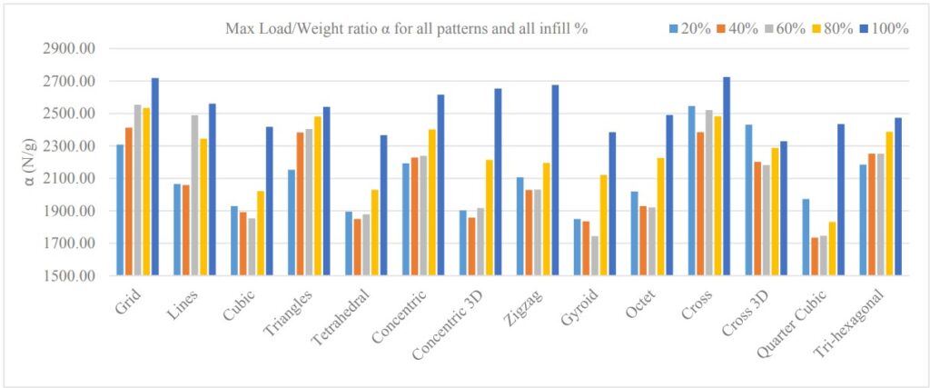
General Observations from the Experiment:
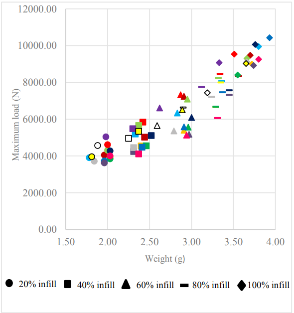
- The test results indicate that as the weight of objects produced with different infill patterns increases, the maximum load they can tolerate also increases.
- The Grid (Red) infill pattern at 40% infill density produced an object weighing 2.42g, capable of withstanding 6000N, making it lighter than other patterns while maintaining the same load capacity. Similarly, a Zigzag (Dark Blue) infill pattern at 60% density provided a comparable load capacity at 3g weight, and a Quarter Cubic infill pattern at 80% density showed similar performance at 3.31g weight, withstanding approximately 6000N.
- 100% infill density does not always provide the highest strength.
- While 3D infill patterns offer more balanced strength distribution in all directions, 2D infill patterns demonstrate superior load-bearing performance.
Conclusion and Comparison
The compression test results show that 2D infill patterns tend to perform better than 3D infill patterns when it comes to strength-to-weight ratio and maximum load capacity.
Patterns like Grid, Cross, and Triangles stood out as the best-performing 2D infill patterns, offering a great balance of lightweight design and durability. This means they’re a solid choice for efficient and strong 3D-printed parts.
Now, let’s take a closer look at each pattern and what these findings mean for them.
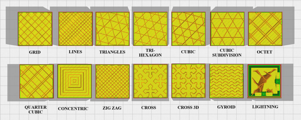
Grid
As seen in the test results, this pattern provides higher mechanical strength at a lower density and weight ratio compared to other patterns. It performs particularly well in 40%-80% infill densities, offering better load-bearing capacity. However, it is important to note that this strength is mainly effective against forces coming from a single direction.
This pattern is suitable for lightweight applications requiring strength. It can be used in automotive and aerospace applications, including engine covers, internal structural supports, and fastening elements. Additionally, it can be advantageous in prototyping and sports equipment.
Lines
While it may not be as strong as the Grid pattern, it still offers good mechanical strength relative to its lightweight structure. Since it belongs to the 2D infill family, it has the advantage of fast printing, as nozzle movements are simpler during printing. It provides moderate mechanical strength.
This pattern is ideal for applications where extreme strength is not critical, but lightweight and cost-efficiency are important. It can be used in prototyping applications and artistic designs that do not require high mechanical durability.
Cubic
As seen in the previous tests, the defined load-to-weight ratio (α) is relatively low against unidirectional forces. However, it provides good resistance against multidirectional, 3D forces. Compared to other patterns, it has a slower print speed and moderate material consumption.
This infill pattern is suitable for mechanical parts exposed to forces from multiple directions. It can be beneficial for robotic arms and joints. Additionally, its complex 3D structure makes it a good choice for optimizing heat distribution and airflow management.
Triangles
Ranked right after Cross and Grid in the compression tests, this pattern forms regular triangular structures throughout the layers, making it highly effective in terms of strength-to-weight ratio. Due to these properties, it is widely used in engineering, design projects, and construction applications.
Tetrahedral
As a 3D infill pattern, this structure is suitable for parts exposed to forces from multiple directions. It fills the object using a tetrahedron (four-faced) geometry, providing a stable and precise design solution. This pattern can be beneficial for high-precision and stable structures.
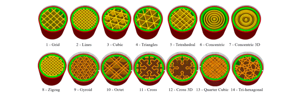
Concentric
This infill pattern builds the object using concentric rings, expanding outward from the center. The compression tests have shown that it exhibits good strength characteristics, making it useful for applications requiring increased mechanical strength in outer layers. While it performs well in compression tests with unidirectional forces, it is not suitable for complex loading conditions. Additionally, it is sometimes preferred for aesthetic purposes.
Concentric 3D
As observed in the compression tests, this pattern does not perform well under unidirectional forces, but it offers better resistance to multidirectional forces. In addition to its ability to optimize heat distribution, it is also used for aesthetic applications.
Zigzag
While this pattern does not provide as much mechanical strength as other patterns, it can be preferred for applications requiring lightweight structures. One notable characteristic observed in the compression tests is that at 80% infill density, it withstands slightly over 2000 N, while at 100% infill density, it resists nearly 3000 N. This indicates that the 100% infill density offers significant advantages compared to lower densities for this pattern.
Gyroid
Although it does not exhibit high strength against unidirectional forces, it performs well under multidirectional forces. Its aesthetic and complex structure, along with its low material requirements, make it an attractive choice for certain applications. Like the Concentric 3D pattern, it can optimize heat distribution. In summary, this pattern is suitable for applications that require lightweight structures with isotropic strength.
Octet
The Octet pattern fills objects with interconnected octahedral structures, providing excellent multidirectional load resistance. It is suitable for applications in heat and fluid management. Additionally, it is ideal for lightweight enclosures that require good resistance against mechanical impacts from multiple directions. However, its complex 3D structure can extend printing times.
Cross
This pattern ranks first in the compression tests with a defined load-to-weight ratio (α) of 2531.92 N, making it highly advantageous due to its high strength, short printing time, and lightweight characteristics. It uses intersecting lines to build the desired object. It is commonly used in prototype production, medical devices, automotive, and aerospace applications.
Cross 3D
Due to its 3D cross-shaped structure, it provides isotropic strength both internally and externally. While it offers aesthetic and functional benefits, it is also effective for producing lightweight parts. However, as shown in the compression test results, its unidirectional strength is relatively weak, which is a disadvantage.
Quarter Cubic
This pattern utilizes tetrahedrons and their truncated versions to create the printed structure. As a 3D infill pattern, its mechanical strength is low, making it unsuitable for applications subjected to significant loads. Another disadvantage is its long bridging distances, which can negatively affect surface quality.
Tri-Hexagonal
As a 2D infill pattern, the tri-hexagonal structure combines hexagons and triangles to form a unique layout. As observed in the compression tests, its compression strength is at a good level. However, it performs poorly in multidirectional strength. The hexagonal geometry provides an aesthetic and orderly appearance, but the gaps between hexagons can be a disadvantage in certain applications.
References
Pernet, B., Nagel, J. K., & Zhang, H. (2022). Compressive strength assessment of 3D printing infill patterns. Procedia CIRP, 105, 682–687.